Hron-Turek FSI3
Repository path: tutorials/fluidStructureInteraction/HronTurekFsi3
Reference: Alkafri et al. (2024), multiRegionFoam: A Unified Multiphysics Framework, Sect. 7.4
Overview
The moving-mesh ALE interface tracking method for multiphase flow is extended here to fluid–structure interaction (FSI). The case follows the benchmark defined by Hron and Turek (2006): a laminar incompressible flow in a 2D channel past a rigid cylinder with an attached elastic beam.
The configuration consists of:
- Channel: $L = 2.5\,\text{m}$, $H = 0.41\,\text{m}$
- Rigid cylinder: centre $C(0.2,\, 0.2)$, radius $r = 0.05\,\text{m}$
- Elastic beam: tip point $A(0.6,\, 0.2)$, length $l = 0.35\,\text{m}$, thickness $h = 0.02\,\text{m}$
A parabolic velocity profile is prescribed at the inlet with maximum velocity $1.5\,\bar{U}$. Three test cases are defined in the benchmark suite—FSI1 (steady), FSI2 (unsteady periodic), and FSI3 (unsteady periodic)—by varying the mean inflow velocity. FSI3 with $\bar{U} = 2\,\text{m/s}$ is considered here.
Computational domain
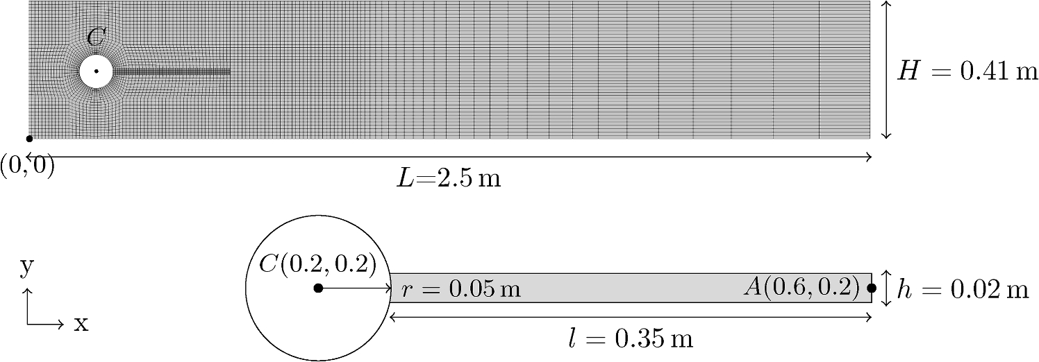
Fig. 18 — Computational domain for the FSI3 case with zoom on the elastic structure. Channel H = 0.41 m, L = 2.5 m; cylinder centre C(0.2, 0.2), r = 0.05 m; beam tip A(0.6, 0.2), l = 0.35 m, h = 0.02 m.
Material properties
Table: Fluid and solid properties for FSI3
| Property | Symbol | Unit | Solid | Fluid |
|---|---|---|---|---|
| Kinematic viscosity | ν | m²/s | – | 10⁻³ |
| Mean inflow velocity | Ū | m/s | – | 2 |
| Density | ρ | kg/m³ | 10³ | 10³ |
| Young’s modulus | E | kg/ms² | 5.6 × 10⁶ | – |
| Poisson ratio | ν | – | 0.4 | – |
Boundary conditions
Table: Boundary conditions for FSI3
| Boundary | Velocity | Kinematic Pressure | Traction |
|---|---|---|---|
| Fluid | |||
| interfaceShadow | movingWallVelocity | zeroGradient | – |
| inlet | parabolicVelocity | zeroGradient | – |
| outlet | zeroGradient | 0 m²/s² | – |
| cylinder, bottom, top | (0 0 0)ᵀ m/s | zeroGradient | – |
| front & back planes | empty | empty | – |
| Solid | |||
| Interface | – | – | regionCoupledTraction |
Mesh refinement study
Three mesh levels are used. The fluid mesh is generated with blockMesh
(coarse) and refined with refineMesh + extrudeMesh:
| Level | Solid cells | Fluid cells | Δt (s) |
|---|---|---|---|
| Coarse | 630 | 5 336 | 1.0 × 10⁻³ |
| Medium | – | 21 344 | 7.5 × 10⁻⁴ |
| Fine | – | 85 376 | 5.0 × 10⁻⁴ |
Simulations are run until a periodic solution is reached. Mean and amplitude values are computed from the last oscillation period; frequency is extracted via fast Fourier transform.
Results
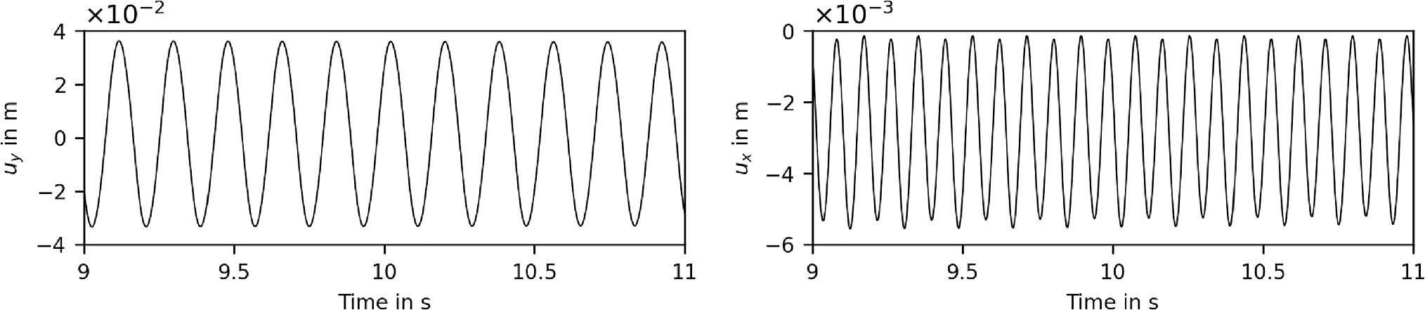
Fig. 19 — x and y displacement of beam tip point A over time obtained from the finest mesh, showing periodic oscillation.
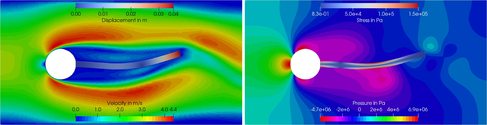
Fig. 20 — Velocity and pressure fields in the fluid alongside displacement and stress fields in the solid structure at the instant of maximum deflection.
Validation results
Table: Displacement of point A — mean ± amplitude [frequency in Hz]
(values in mm and Hz, matching benchmark format mean ± amplitude [frequency])
| Case | u_y (×10⁻³ m) | u_x (×10⁻³ m) |
|---|---|---|
| Coarse | 1.67 ± 28.55 [5.9] | −1.99 ± 1.84 [11.5] |
| Medium | 1.53 ± 33.41 [5.3] | −2.66 ± 2.45 [10.9] |
| Fine | 1.47 ± 34.37 [5.3] | −2.67 ± 2.53 [10.9] |
| Benchmark | 1.48 ± 34.35 [5.3] | −2.69 ± 2.53 [10.9] |
As the fluid mesh resolution increases the computed displacements converge towards the benchmark values.
Reference
J. Hron, S. Turek (2006). A monolithic FEM/multigrid solver for an ALE formulation of fluid-structure interaction with applications in biomechanics. In: Fluid-Structure Interaction, Lecture Notes in Computational Science and Engineering, vol 53. Springer, Berlin, Heidelberg.
Running the case
cd $FOAM_RUN/../multiPhysicsFoam/tutorials/fluidStructureInteraction/HronTurekFsi3
./Allrun